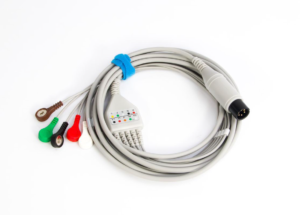
What is a jumper wire?
A jumper is a cable used to connect two points in a circuit. Its primary function is to establish a complete path between circuit boards and devices, ensuring stable power transmission or signal transfer.
During prototyping, integrated circuits and components are connected to the motherboard via jumpers. In finished devices, jumpers can be used to connect the power supply module to the motherboard. Additionally, jumpers can be used to connect routers to computers.
In prototyping, integrated circuits and components are connected to the motherboard via jumpers. In finished devices, jumpers can be used to connect power supply modules to the motherboard. Additionally, jumpers can be used to connect routers and computers.
Functionally, jumpers can be categorized as follows:
lPower jumpers: Used to transmit electrical power.
lSignal jumpers: Used to transmit data or control signals.
Ground jumpers: Used to ensure reliable grounding of the metal casing or structural components of electrical equipment.
How do jumpers work?
The operating principle of a jumper involves establishing a low-resistance path using conductive materials such as copper or aluminum. This allows current or signals to flow from one point to another, forming a closed circuit that transmits energy or information.
First, from the perspective of current transmission, the operation of jumpers follows Ohm’s Law (V = I × R), where their performance is determined by voltage (V), current (I), and resistance (R). To ensure efficient energy transfer, jumpers are typically constrained by material properties and length. Therefore, the cross-sectional area (wire gauge) and length are critical design parameters.
In terms of signal transmission, jumper cables operate in a more complex manner. For digital signals, patch cables transmit binary data (0s and 1s) represented by voltage changes. For example, in 5V TTL logic, a high voltage (approximately 5V) represents 1, while a low voltage (approximately 0V) represents 0. Patch cables must maintain signal integrity to prevent loss or attenuation. This involves impedance matching—if the patch cable’s characteristic impedance does not match the load impedance, data errors can occur. In high-frequency applications (such as USB or Ethernet cables), cables may employ twisted-pair or coaxial structures to minimize electromagnetic interference (EMI) and radio frequency interference (RFI). For instance, CAT6 Ethernet cables use four twisted pairs, where twisting counteracts external interference to ensure high-speed data transmission.
The functionality of patch cords also involves their connection mechanisms. Most patch cords utilize connectors (such as DuPont connectors or RJ45) to ensure stable connections. The metal contacts within the connector are joined to the patch cable wires through crimping or soldering. When inserted into a socket, a spring-loaded mechanism ensures connection stability. Poor contact may result in intermittent failures or complete disconnection. Furthermore, patch cables can serve not only to transmit signals but also to participate in circuit functionality. For instance, in patch cable configurations, jumper blocks (a specialized type of patch cable) are used to select circuit modes, such as enabling a specific function by connecting two pins.
Jumpers are also susceptible to environmental factors during use. The wiring may expand with temperature changes, leading to intermittent connection failures or complete disconnections. Jumpers are typically designed with an insulating layer (such as PVC). This insulation not only provides enhanced mechanical protection but also effectively prevents accidental short circuits caused by exposed conductors coming into contact with other components.
In summary, patch cables function by establishing a reliable electrical pathway. Through optimized materials, design, and connection methods, they ensure efficient transmission of current and signals. Understanding these principles helps users select and utilize patch cables correctly, avoiding common issues such as signal loss or connection failures. In the next section, we will explore various connector types, which are critical components for patch cable operation.
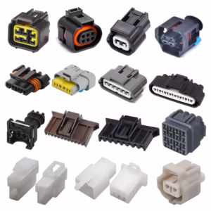
Connector Type
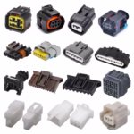
Connectors form the core component of patch cables, ensuring reliable connections between the cables and devices. Selecting the appropriate connector type is critical to system performance, as it impacts signal integrity, durability, and compatibility. Below are several common patch cable connector types, which we will discuss in detail regarding their characteristics, application scenarios, and respective advantages and disadvantages.
Dupont Connectors
DuPont connectors are commonly used on breadboards and Arduino boards to connect sensors, actuators, or power sources. While their low cost, ease of fabrication, and widespread availability are advantages, DuPont connectors are not well-suited for high-vibration environments due to their weak retention capabilities, which can lead to loosening and disconnection. Standard DuPont jumper wires typically use 22 AWG wire with a 2.54 mm (0.1 inch) pitch, which precisely matches the pin spacing of most integrated circuits.
RJ45 Connector
The RJ45 connector is the most common patch cable connector in Ethernet networks, used to connect computers, routers, switches, and modems. It features eight pins and supports twisted-pair cables, typically used for data signal transmission. The RJ45 connector employs a snap-in mechanism to ensure a secure and stable connection. RJ45 patch cables are categorized by supported bandwidth and transmission distance into CAT5e, CAT6, CAT6A, and CAT7 (e.g., CAT6 cables support up to 10 Gbps speeds over distances of 55 meters). While RJ45 connectors offer advantages like easy installation and high reliability, proper wiring sequences (such as T568A or T568B standards) must be followed during use to prevent signal crosstalk. Additionally, shielded RJ45 connectors can be employed in industrial settings to reduce EMI interference.
USB Connector
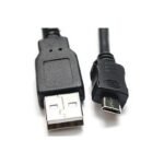
USB connectors are universal jumper connectors used for data transfer, charging, and device connectivity. Common USB connectors include USB-A, USB-B, USB-C, and Micro-USB. Among these, USB-A serves as the standard host-side connector, frequently used for connecting computers and external devices. USB cables offer transfer rates ranging from 480 Mbps for USB 2.0 to 40 Gbps for USB4, commonly used to connect external hard drives, smartphones, or printers. While USB connectors offer advantages like hot-swappable functionality, high bandwidth, and power delivery, compatibility issues may arise between different versions. For example, when using a USB-C cable, ensure both the device and cable support the same protocol.
HDMI and Display Connectors
HDMI (High-Definition Multimedia Interface) connectors are cables used for audio and video output, enabling connections between devices such as televisions, monitors, and gaming consoles. HDMI cables transmit digital video and audio signals, supporting high resolutions (like 4K and 8K) and High Dynamic Range (HDR). HDMI connectors come in three sizes: Standard, Mini, and Micro, typically featuring a 19-pin design. While offering plug-and-play functionality and high bandwidth support (up to 48 Gbps for HDMI 2.1), they have significant length limitations (generally not exceeding 15 meters without an amplifier).
Power Connector
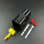
Power jumper connectors are used for transmitting electrical power. Common types include DC power plugs (such as barrel connectors), Molex connectors, and Anderson Powerpole connectors. DC power plugs are typically used in laptops and routers, offering various voltage and current ratings. Molex connectors are common in computer power supplies, connecting hard drives and optical drives. Anderson Powerpole connectors are favored for amateur radio and high-current applications, renowned for their stackable design and high current-carrying capacity. These connectors prioritize safety and reliability, often incorporating locking mechanisms to prevent accidental disconnection. Potential drawbacks may include larger dimensions or more complex installation.
Other Specialized Connectors
In addition to the aforementioned types, numerous specialized jumper connectors exist, such as BNC for RF applications, D-Sub (e.g., DB9) for serial communication, and JST connectors for consumer electronics. BNC connectors utilize bayonet coupling, making them suitable for high-frequency signal testing; D-Sub connectors are employed in legacy computer ports like VGA and serial interfaces. JST connectors are miniature crimp connectors commonly found in drones and battery packs.
When selecting connector types, factors to consider include current capacity, voltage rating, frequency response, environmental conditions, and cost. For instance, in high-vibration industrial environments, locking connectors may be preferred, while shielded connectors take priority in high-frequency applications. Ultimately, the connector type determines the suitability and performance of the jumper cable, and users should choose based on specific requirements. In the next section, we will discuss whether jumper cables can be soldered, which relates to connector installation and customization.
Can jumper wires be soldered?
The answer is yes, jumpers can be soldered, but this depends on the jumper type, application scenario, and user requirements. Soldering is a common method for electronic connections, where molten solder (typically tin-lead or lead-free alloys) bonds jumper wires to connectors or circuit boards, forming permanent or semi-permanent connections. Soldering jumpers provides robust, low-resistance contacts suitable for high-reliability applications, though it may sacrifice flexibility and reusability. In this section, we will explore in detail the feasibility of soldering jumpers, its advantages and disadvantages, the operational steps involved, and when it is appropriate or inappropriate to solder jumpers.
Feasibility of Welding Jumper Wires
Most jumpers are solderable, especially those using standard wires such as stranded or solid copper wire. Soldering is commonly used for custom jumpers or repairing damaged connections. For example, in DIY electronics projects, we can purchase bulk wire and connectors, then solder them ourselves to create jumpers of specific lengths. In industrial settings, soldering ensures jumper reliability in harsh environments like high temperatures or intense vibration. However, some pre-made jumpers—such as those with crimp connectors—are unsuitable for soldering, as it can damage the original structure or cause thermal damage.
Advantages of Welded Jumpers
Soldered connections typically feature low resistance and high mechanical strength, effectively preventing oxidation and corrosion of jumper wires to extend their lifespan. This characteristic is particularly crucial in power supply or high-frequency signal applications, where loose connections may cause voltage instability, signal loss, or malfunctions. Soldered jumper wires also allow for custom lengths and configurations, offering greater flexibility in practical operations. For instance, in circuit board repair work, soldered jumpers can bypass damaged traces. Since solder joints can be made extremely compact, soldering is also well-suited for space-constrained scenarios.
Disadvantages of Welded Jumpers
Although soldering offers numerous advantages, it also has some drawbacks. First, soldering is a permanent operation; once completed, it is difficult to modify or remove, making it unsuitable for testing environments requiring frequent changes. Second, soldering requires skill and tools (such as a soldering iron, solder wire, and flux). Improper handling may cause short circuits or damage components. For instance, excessive heat can melt jumper insulation or harm sensitive electronic parts. Additionally, soldered jumpers may fail to meet certain standards (e.g., TIA/EIA standards for network jumpers). In standardized systems, crimped connectors are often more recommended.
Operating Procedure for Soldering Jumper Wires
Here’s are the quick and dirty steps if you opt to solder in some jumper wire.
Prepare your tools and materials: You’re going to need a soldering iron (one that’s got variable heat settings), some fairly fine solder (0.5-1mm diameter but about ten centimetres’ worth), flux, wire strippers, and some sort of insulation (heat-shrink tubing if you have it or failing that, some electrical tape).
Strip the wires: Strip off a little insulation to expose about 3-5 mm on the ends of your jumper wires. Use your wire strippers! Mind the wires not to break them!
Pre-tinning: Precoat the wires and connector pins with solder beforehand (heat each pin to get the solder applied) This improves soldering quality.
Soldering: Position the wire across the pad. Heat both with the soldering iron and then apply the solder to melt and flow across the connection. Make sure the joint is nice and smooth clean, shiny and free of burrs.
Insulate: Apply some heat shrink tubing or electrical tape on the solder joint to avoid shorting. Shrinkage ratio : 2:1, shrink tubing can be shrunk by heat gun or lighter.
Test: Use the multimeter to measure connection resistance and continuity, no short circuit or open circuit.
When should jumper wires be soldered?
Welded jumpers are not suitable for all scenarios, but they can be considered in the following situations:
– Permanent installations such as home wiring or embedded systems.
– Applications requiring high reliability, such as aerospace or medical equipment.
– Situations where standard patch cords fail to meet requirements, necessitating custom-made solutions.
Conversely, crimped or plug-in patch cords are more suitable for testing or scenarios involving frequent plugging and unplugging. For instance, network patch cords typically use crimped RJ45 connectors, as soldering may degrade signal performance.
In summary, jumpers can be soldered, but one must weigh their flexibility, reliability, and skill requirements based on the application scenario. For beginners, it is recommended to start practicing soldering techniques with simple projects. In the next section, we will explore the significance of jumper colors, which proves highly useful for organizing and managing jumpers.
Jumper wire color
The colors of patch cords serve not only aesthetic purposes but also function as design elements for coding, identification, and organizing connections. Color-coding systems enable rapid differentiation of patch cord functions, voltage levels, signal types, or system affiliations, thereby reducing errors, enhancing work efficiency, and improving safety. Across various application fields—such as electronics, electrical engineering, and network cabling—patch cord colors adhere to specific standards or conventions. This section will explore the common meanings of jumper colors, relevant industry standards, and how to leverage color to optimize jumper management.
The Basic Principles of Color Coding
Jumper color coding relies on visual recognition, using different colored insulation layers to convey distinct information. This approach leverages human sensitivity to and memory of colors, enabling rapid identification of specific jumpers within complex systems. For instance, on a circuit board, a red jumper wire might indicate the positive power supply terminal, black signifies ground, and yellow could denote a signal line. This coding simplifies debugging and maintenance, particularly when systems involve dozens or even hundreds of jumper wires. Color coding is typically combined with labels or documentation to ensure accuracy.
Common Jumper Wire Colors and Their Meanings
Color standards differ by industry or geographic region, but some remain in widespread use. For example, red is frequently used to indicate positive power terminals or high-voltage lines. red jumpers are used for the battery /powerrails of the dcdc board. Within systems, red might mean essential links or alarm circuits. Most of the time black is applied to ground (GND) or reference ground voltage. Yellow is for signal lines or data lines such as sensor outputs, control signals etc; blue: low-voltage signal line/circuit tapping; green: ground/safety ground, and sometimes video signal. Nothing is ever that simple in networking, though – green can also mean network connections; and white is typically used for neutral lines or general signal lines. In stereo applications, white is for left-channel audio jumper wires, etc.
In AC power systems, color coding is more stringent: black or red denotes the hot wire, white or gray denotes the neutral wire, and green or green-yellow denotes the ground wire (per NEC standards). In network cabling, the TIA/EIA-606 standard defines colors for management purposes: for example, blue is used for workstation connections, green for network equipment, and yellow for cross-connections.
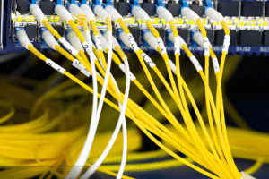
The Application of Color in Patch Cord Management
The color of the jumper cable is important in cable management for data centers or server rooms. Color coding allows an administrator to quickly ascertain what the jumper is used for, what its priority is, or even which VLAN has been plumbed. For instance, red to connect critical servers, blue for user access and yellow for backup links. This make for easier troubleshooting, upgrades and compliance auditing. Then throughout the day, while training new employees etc. blocks can be moved to accommodate for the task at hand making the learning curve a bit less steep.
In electronic prototyping, color coding makes breadboard wiring more intuitive. Beginners often use colored jumper wires to distinguish power, ground, and signal paths, preventing short circuits or incorrect connections. For example, in Arduino projects, red jumper wires connect to the 5V pin, black to GND, and other colors are used for digital I/O. This not only improves efficiency but also reduces error rates.
Custom Color Coding
Although standards exist, many organizations adopt custom color coding to suit specific needs. For example, a factory might use purple jumper wires to indicate safety systems and brown for sensor networks. When establishing custom coding, it should be documented and teams trained to ensure consistency. Color selection should also consider colorblind users, avoiding reliance on red-green color differences.
The Effect of Color on Performance
(Note: the color of the jumper wire has no bearing on its electrical properties, but the insulation color might be associated with material characteristics.) For instance, different colors might use different additives that affect heat resistance or UV resistance. But for the most part colour is only a way to identify function.
In summary, jumper wire colors serve as a powerful organizational tool, enhancing safety, maintainability, and efficiency through standardized or custom coding. Users should consider color schemes when designing systems and adhere to industry best practices. In the next section, we will explore jumper wire component types to further expand our understanding of jumper wire diversity.
Jumper Component Type
Jumper elements are of various kinds, depending on their structure, application and operation properties. This knowledge of types assists the end user in choosing the best type of jumper for their application based on performance, cost and convenience. Jumper components can be divided into several aspects, such as the number of conductors, shield method, connector structure and applied domain. In this section, we will discuss typical jumper component types that have some features and advantages as well as drawbacks like those described above, in detail.
Classified by Number of Wires
Single core jumper wires: Composed of one piece of solid conductor, usually made of copper or with copper cladding such as aluminum. The wires are stiff, but they’re flexy enough to pull wire out and backtrack or reuse in a new project. They easy to work with, whether for prototyping or for something more permanent. For instance, in Arduino projects single-core jumper wires are used to provide connections from pins to breadboard. They are stable and have low resistance, but the bending behavior is such that they easily can break with repeated flexure.
Multi strand flexible jumpers: Made from several strands of fine wire twisted together, make it more flexible and can withstand bending and vibration. Commonly found in mobile devices or in apps that you plug/unplug frequently, like USB key cables or earphone cables. They have the benefit of being more durable and are good for dynamic, however they may tend to be a little bit stiffer with a higher resistant or price.
Ribbon cables:Two or more parallel insulated wires bundled together and then sheathed as a unit. Ribbon cables are used for many internal computer connections, such as hard drivesand GPIO. Pros are high connection density and ease of routing, cons are flexibility and lack of airflow.
Classified by Shielding Method
Unshielded Patch Cables – These are the simplest, with just conductors and insulation without any additional protection. They are less expensive and more flexible than shielded patch cords, and are adequate for low-noise environments such as transmitting an analog audio signal from a mixer to an amp, or a line-level signal from a music source (such as an mp3 player) to some speakers. For instance, Statement 4105 DuPont patch cables are not shielded. The disadvantage is vulnerable to EMI under high frequency or noise environment.
Foil/braid shielded patch cables: This type of cord features a layer of shielding consisting of a foil and braid, protecting the conductor from interference such as EMI/RFI. These shielded patch cables are used in complex environments such as medical, audio equipment or industrial control systems. For example, shielded Ethernet patch cords (FTP or STP) are used in noisy environments. The benefits are better signal integrity at the expense of being heavier and more expensive and less flexible.
By Application Field
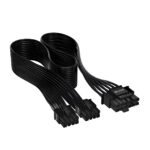
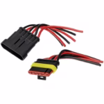
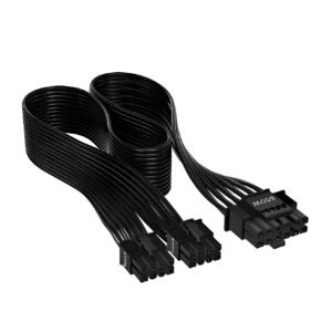
Power Jumper cable: For power connection, it can be done with wire(s) from a larger diameter (smaller AWG number) and high current connectors. Commonly used in PC power supply, rechargeable battery or charging device etc. Includes molex power jumpers for PC as easily. High current, and safety (maybe even including fuses or locks) are the requirements here.
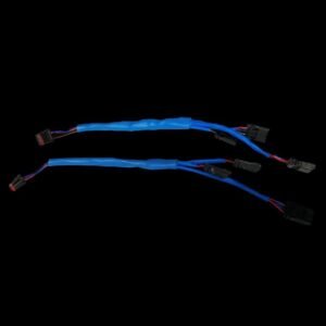
Signal Jumpers: try to maintain the signal stables and impedance for data or control transmission. These are things like ethernet jumpers, video jumpers (HDMI etc) and sensor jumpers. They usully shield by a pair and twisted pairs are in shields to minimize the distortion.
Data Jumpers: Data jump to high speed USB, SATA, fiber. Data Jumpers can also support high bandwidth and may include error correction mechanisms. For example, SATA jumpers are used to connect storage drives in order for quick data access.
Network Jumpers: Computer networks, such as an ethernet jumpers (RJ45) and fiber optic jumpers. The network jumpers are performance-rated (from CAT5e to CAT8) and suitable for various speeds, distances and cabling. They are commonly employed in LAN and data center networks.
By Connector Design Classification
– Pre-terminated patch cables: Factory-assembled cables with fixed lengths and connectors, offering plug-and-play convenience. Pre-terminated cables provide consistent quality and meet standards, but lack customization options. For example, standard USB cables are pre-terminated.
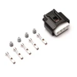
– Field-terminated patch cables: Cables where users install connectors on-site, allowing for custom lengths. These cables require crimping or soldering tools and are suitable for temporary installations or specialized needs. For instance, field-terminated RJ45 patch cords are used for network expansion.
– Adapter patch cords: Patch cords featuring specialized adapters to convert connector types, such as USB-C to USB-A adapters. Adapter patch cords enhance compatibility but may introduce signal loss.
Special Jumper Types
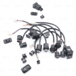
Jumper Cap: A small wire link used to shortcircuit between two pins on a PCB, usually comprises plastic or metal pole. A jumper cap is used to enable or disable a configuration settings, such as BIOS jumpers on motherboards.
Fiber Optic Patch Cables: Utilize glass or plastic fibers to relay light and are used for high-speed networking & telecommunications. These include single-mode and multi-mode, as well as connectors including LC or SC. Advantages are increased bandwidth, long haul distance but they are expensive and fragile.
High Temperature – Patch Cables: Employ special insulation materials (e.g., Teflon) to protect the cable structure at high temperatures (located nearby turbines, exhaust lines, etc.).
When choosing the patch cord components, the current carrying capacity, signal frequency, environmental requirement and budget and installation consideration all are to be taken into account. For example, unshielded CAT6 patch cords may be used in home networks, while shielded multi cores are applicable to industrial automation. In conclusion, patch cord materials have different types of diversity to meet various needs and users need to refer it for the corresponding application. In the next few sections we will discuss how to use patch cords – applying those best practices and practical guidelines.
How to Use Jumper Wires
Using jumpers may seem straightforward, but proper handling is crucial for ensuring system reliability, safety, and performance. Whether you’re an electronics enthusiast, network administrator, or engineer, mastering jumper usage helps you avoid common mistakes like short circuits, signal attenuation, or connection failures. This section provides a comprehensive guide covering jumper selection, installation, testing, and maintenance—including step-by-step instructions, tool requirements, and important considerations. We’ll progress from foundational to advanced topics, ensuring the content is accessible to users of varying skill levels.
Step 1: Select the correct jumper
When using jumper cables, select the type most suitable for your use. Consider the following factors:
Voltage and Current Capacity: Check whether the voltage rating or current capacity matters in a signal. Use jumper cables with adequate wire gauge (AWG) rating, such as 16 AWG for moderate currents; use shielded jumper cables for high-frequency signals to reduce the influence of interference.
Length: Do not make the patch cable too long or short either, since longer one will cause signal loss and shorter one will add tension. The guideline, however, is to take the briefest rightful length.
Connector: To suit device interfaces, e.g. RJ45 patch cords for Ethernet ports and DuPont patch cords for microcontrollers. Please make sure that connector gender, pin count and notches are the same as your old cable.
Environment : Choose weatherproof patch cables for outdoor or high temp environments, with UV-stable jackets and/or waterproof connectors.
Standards Compliance: Choose patch cords for networking or safety critical applications that comply with industry standards, such as TIA/EIA for Ethernet and UL certification for power.
For instance, for home network setup you may use a 1-meter CAT6 unshielded patch cable to link a router and computer; and on an Arduino work, select the flexible 22 AWG multi-conductor DuPont patch cables.
Step 2: Prepare Tools and Workspace
Before using jumpers, prepare necessary tools and ensure the work area is safe:
– Basic Tools: Include wire strippers, crimping tools, a multimeter, a soldering iron (if soldering), and a cable tester.
– Safety Equipment: Wear an anti-static wrist strap to prevent ESD damage to sensitive components; disconnect power for power supply applications.
– Workspace Setup: Maintain a clean, well-lit area using an anti-static mat. Review equipment manuals for specific connection requirements.
Step 3: Install the jumper
The steps for installing patch cords varies depending on the type:
For pre-terminated patch cords : Snap directly into corresponding port. Line up pins and press down on them evenly until the latch clicks. This makes them easy to disconnect, even if a patch cord is inserted, by feeling or hearing an audible “click”.
For field-terminated patch cords:
Strip the wires: Take off the insulation of the wire end to expose about appropriate length (around 1.5 cm for RJ45) with a wire stripper.
Arrange wires: Straight-through / multi-core jumpers, all the wires need to be arranged in same order (T568B for Ethernet).
Crimping: Insert cables into the combined, then place them in crimp connections. Verify no copper is exposed.
Insulation: Heat-shrink or tape connections as required.
Solder jumpers: After soldering all pins and testing connections to shields or other devices, perform the following steps, making certain you have secure joints with proper insulation.
Misjudge only the diameter bend jumpers to avoid unnecessary twists, tears connectors or use Mismatch tools. For instance when crimping RJ45 connectors, do use dedicated crimp pliers to ensure there is no damage from the contact.
Step 4: Test the connection
After installation, test the patch cord to ensure proper functionality:
– Continuity Test: Use a multimeter to check resistance; low resistance indicates a good connection; infinite resistance indicates an open circuit.
– Signal Testing: For data jumpers, use a cable tester to verify transmission quality. For example, a network tester can detect wiring errors or attenuation in Ethernet jumpers.
– Functional Testing: Power on the system or transmit data, observing device responses. If issues arise, check for loose connections or damaged jumpers.
Step 5: Organize and Manage Patch Cables
Controlled patch cord management is an important part of providing highly reliable and maintainable systems:
Labeling: Use labels to portray the function of the patch cord, source and destination (this is especially important with complex cabling).
Cable Management-Keep jumpers in order with cable ties, management panels or trays to avoid tangles and overstressing.
Documentation: Document jumper pattern for maintenance in the future. Use a CMDB (Configuration Management Database) to manage jumpers in data centers.
Best Practices and Considerations
– Safety First: Always disconnect power when handling power jumpers; protect circuits with fuses or circuit breakers.
– Minimize Interference: Route power jumpers separately from signal jumpers to reduce noise coupling.
– Regular Inspection: Periodically check jumpers for wear, oxidation, or loose connections; promptly replace damaged components.
– Follow Standards: In professional environments, adhere to industry standards such as ANSI/TIA for network cabling to ensure compatibility and performance.
Practical Application Examples
Home Network Setup: Chose CAT6 patch cables and plugged them into the router and computer; verified Internet access; marked each cable’s purpose.
Arduino Projects: Link insect repellent sensors and boards with color-coded DuPont jumper wires; test the signal using code; prevent short circuits by checking wiring characteristics.
Industrial Control: Connect PLCs and sensors with shielded patch cords, test signal integrity after crimping connectors, protect terminations with jackets in harsh environments.
In short, you need to do your patch cabling in a thoughtful manner. By paying attention to these steps and best practices, you will get the most out of your patch cable. As the backbone of your network and data systems, adequately patch cabling helps to guarantee that projects or equipment are running efficiently.
Conclusion
Jumper components serve as the cornerstone of electronics and networking, their significance far exceeding their simple appearance. By definition, a jumper is a wire or cable connecting two points in a circuit to transmit current, signals, or data; its operation relies on establishing electrical pathways to ensure efficient energy and information flow. We explored various connector types—such as DuPont, RJ45, and USB—each optimized for specific applications, highlighting the diversity of jumpers. Regarding soldering, jumpers can be soldered to provide reliable connections, though this requires balancing flexibility with skill requirements. Color coding serves as an efficient management tool, enhancing safety and organization through visual differentiation of functions. Jumper component types are extensive, ranging from single-core to shielded, and from power to data, meeting diverse environmental needs. Finally, guidelines for jumper usage emphasize the importance of proper selection, installation, and maintenance to ensure system reliability.