As a quality expert with 11 years of experience in quality management, I will analyze the principles and solutions for terminal pin withdrawal from three perspectives.
What is Terminal Backout?
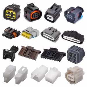
Terminal Backout refers to the abnormal separation of terminals from the housing after connector assembly, resulting in connector failure.
Three Common Causes of Terminal Backout
This failure mode typically arises from three factors:
- ① Insufficient retention force of terminals within the housing;
- ② Mating interference;
- ③ Product application issues.
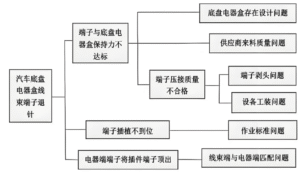
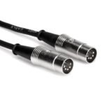
Terminal Backout (Figure 2) is a relatively common failure mode in wiring harnesses.
Terminal Backout refers to the failure of terminals to reach their intended positions, resulting in connector malfunction. Automotive wiring harnesses primarily rely on manual operations, making quality control challenging. To better prevent and manage terminal pin retraction issues, control measures are implemented across the following key areas: design selection, process protection, terminal crimping, assembly, electrical testing, and final installation.
Terminal Backout : Design Selection
Quality is designed and manufactured, not inspected. To prevent Terminal Backout, the first step is design selection. Five key evaluation metrics are listed below (Figure 3).
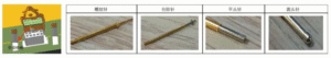
Insertion Force (Figure 3):
This indicates the ease of terminal assembly. Lower resistance during pre-assembly into connectors facilitates proper seating. Thus, insertion force is the primary selection criterion—lower force reduces assembly difficulty and minimizes terminal dislodgement risk.
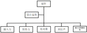
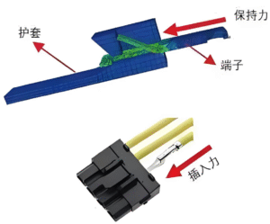
Retention Force (Figure 4):
The horizontal pull-out force of the terminal from the housing (i.e., retention force). A higher retention force makes it less likely for the terminal to be dislodged during connector mating. When selecting designs, opt for connectors and terminals with greater retention force.
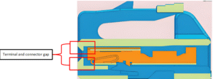
Play (Figure 5):
When mating male and female connectors, significant terminal play within the housing can cause terminals to be pushed out. To reduce the risk of pins being dislodged during mating, prioritize selecting terminals and connectors from the same manufacturer during design selection (purpose: to ensure minimal terminal play when the connector and terminal are matched).
Positioning Sound:
The audible confirmation when terminals are fully seated during assembly. Currently, terminal pre-installation relies entirely on manual labor, posing a risk of terminal pins slipping out. To help employees better identify proper pre-installation seating, we introduce a performance metric: the positioning sound. This assembly confirmation sound must exceed ambient noise levels (which should range between 30dB-50dB): 7dB above ambient before moisture exposure, 5dB above after moisture exposure, or as mutually agreed upon by both parties.
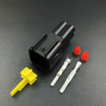
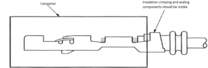
Terminal Hole Misinsertion Prevention Structure (Figure 6):
When inserted in the wrong orientation, the terminal must not enter the terminal hole, and the insulating support and sealing components must remain exposed outside the terminal hole. During troubleshooting, we observed that some terminals could still be inserted into the connector when misaligned, making it difficult to detect during retraction. Therefore, during design selection, the ease of misaligned insertion must be considered to ensure terminals cannot be fully seated when assembled incorrectly.
Process Protection
Two factors contribute to terminal pin retraction: spring sheet deformation and terminal misalignment.
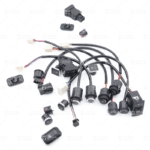
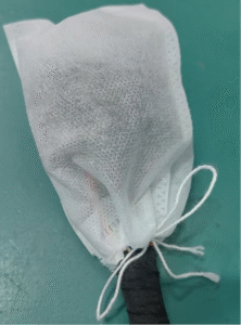
Both result from external forces during processing causing terminal deformation. To protect terminal spring sheets from deformation due to external forces, protective caps (Figure 7) must cover terminal heads after crimping. These caps should only be removed during assembly. After harness assembly is complete, seal the male connector housing with sealing tape or a non-woven fabric bag (Figure 8) to prevent terminals from becoming misaligned due to external impacts during transportation.
Terminal Crimping
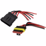
Terminal crimping is a critical step in automotive wiring harness production. The primary process involves connecting electrical systems to terminals using fully automated crimping equipment to integrate terminals with circuits. Terminal crimping is also a contributing factor to terminal pin retraction during harness manufacturing. “Banana-shaped” terminals are a common issue arising from excessive bending during crimping, typically caused by crimping die problems (Figure 9). During assembly, terminal crimping deformation can result in increased insertion/extraction force for connectors in mild cases. In severe instances, male terminals may fail to engage the effective area of female terminals, causing terminal disengagement. Adjusting the limit pins on the crimping equipment can resolve such issues.
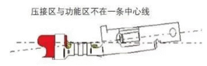
Case Study: The final assembly workshop reported terminal pins retracting during AC socket insertion for a specific vehicle model. Two terminal states were observed. Comparison revealed that faulty terminals exhibited a banana-shaped deformation. Testing confirmed that straightening the defective terminals eliminated pin retraction during insertion. Subsequently, adjusting the crimping equipment’s limit pin resolved the issue completely.

Assembly
Wire harness assembly primarily relies on manual labor. To better mitigate the risk of improper terminal assembly, the industry generally follows the “one insert, two listen, three pull back” procedure.
Insert refers to inserting the terminal,
Listen refers to hearing the sound confirming proper insertion,
Pull refers to gently tugging the terminal after insertion to check for dislodgement.
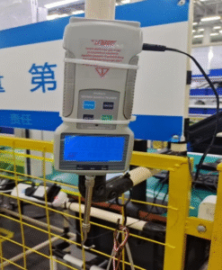
With workers inserting terminals thousands of times daily, operational fatigue is common. To help employees develop muscle memory, we implemented adjustments: First, “pull once” before each shift and during breaks. Here, “pull” means using a pull tester installed at the workstation. Before shifts and after breaks, employees must manually pull the force gauge to ensure the insertion force becomes muscle memory. Second, we changed the sequence to “Look, Insert, Listen, Pull Back.” Adding “Look” helps identify terminal deformation and ensures banana terminals are inserted in the correct orientation.
Electrical Testing
Electrical testing of wiring harnesses is a critical stage in harness manufacturing. To ensure effective detection and prevention of terminal misalignment and terminal pin disengagement, the electrical testing equipment must meet the following conditions:
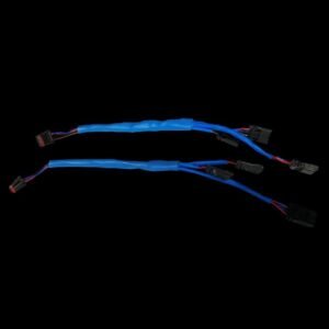
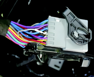
First, the male terminal fixture must be equipped with an anti-misalignment grid (as shown in Figure 12) to prevent misaligned terminals from making contact. Second, electrical test probes must use threaded stepped pins to prevent terminals from being pushed out during testing. Third, calculate the terminal’s movement within the sheath based on dimensional chains to fabricate probes, and establish a routine maintenance schedule for probes.
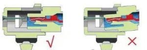
Case Study: Workshop A reported difficulty installing the left front door control panel connector for a specific vehicle model (terminals popping out). On-site investigation confirmed that this model had been transferred from Workshop B to Workshop A for assembly. During assembly, improper alignment caused the female terminals to be pushed out. The issue resolved after ensuring proper alignment during installation. This case clearly demonstrates that when assembling wiring harnesses, employees must ensure male and female connector sleeves are properly aligned (Figure 13) during insertion. This practice reduces the risk of terminals being pushed out due to misalignment during the assembly process.
This paper conducts an in-depth analysis of factors affecting terminal pin shedding in automotive wiring harnesses. It explores specific preventive and control measures across design selection, harness manufacturing, process protection, and assembly techniques. The study provides guidance for harness design selection, offers concrete recommendations for manufacturing process control, and presents specific methodologies for fault mode analysis.
Contact us immediately to learn how we can meet your cable and harness requirements. Follow us on Youtube .