As an expert with 11 years of design experience, I will take you on a deep dive into this intricate control core. We’ll trace the final destinations of the relay’s four critical terminals, deciphering the underlying numbering logic and operational principles.
Chapter 1: The Role and Structure of Electric Fan Relays
First, what is a relay? What does it do? Essentially, a relay is an electromagnetic switch. When an electric fan operates, the command signals emitted by the microprocessor (MCU) or timer chip on the mainboard are too weak (low voltage, low current) to directly drive the fan motor. Therefore, the relay serves as an intermediary. It receives these weak signals, activates, and then controls the motor by closing or opening its own contacts to supply high-voltage power (220V AC).
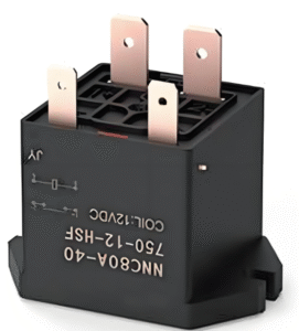
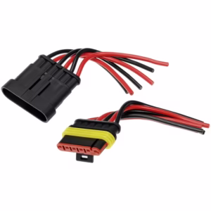
Typically, household electric fans use single-pole double-throw (SPDT) relays, which usually feature 4 or 5 external pins (multiple pins may include fixed terminals). Where exactly do the four wires connected to the bottom of the relay lead? These wires must correspond to the following standard pin numbers and internal structure:
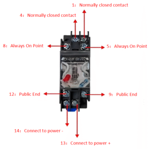
- Control Terminal: The part that receives commands. It has two pins:
- Pin Numbers: 13 (A1) and 14 (A2), the most universally adopted international relay coil numbering.
- Function: When a rated DC voltage (typically DC 5V or DC 12V, determined by the control board) passes through these two pins, the coil generates a magnetic field due to the current flow, thereby altering the switch contact state (closing). When the voltage is removed, the contacts spring back to their original position (open).
- Common Terminal (COM): The power output section of the relay. It has one pin:
- Pin Number: 1 (COM)
- Function: Connects to the live wire from the power source (after being controlled by switches, etc.), serving as the “gateway” for current input.
- Normally Closed Terminal (NC): The default connection point when the relay is de-energized.
- Pin Number: 4 (NC)
- Function: When no voltage is applied to the coil (pins 13 and 14), the Common Terminal (1) is electrically connected to the Normally Closed Terminal (4).
- Normally Open Terminal (NO): This is the connection point that closes when the relay is energized.
- Pin Number: 3 (NO)
- Function: When the coil (13 and 14) is energized, the common terminal (1) switches from connecting to the NC terminal (4) to connecting to the NO terminal (3).
Now that we understand the relay’s internal structure, I will proceed to explain the function of each wire step by step, following the wiring path.
Chapter 2: Wire Connection Schematics
- Coil Control Wires (Pins 13 and 14) Connection Schematics: These two thinnest wires carry control current from the main control circuit board.
- Wire Gauge Characteristics: Typically uses thinner wire (e.g., AWG 22-24), colored blue, yellow, white, etc.
- Where Do They Lead?
-
- Pin 13 (A1): This wire connects to the positive terminal (P) of the DC power supply on the control board, providing a stable “standby power” for the relay coil.
- Pin 14 (A2): This is the core wire! It connects to the output pin of a driver transistor or integrated circuit (IC) on the control board that protects the MCU. Therefore, this wire does not connect directly to the negative terminal (N) of the DC power supply.
- Workflow: When the MCU decides to activate the relay (e.g., pressing the “Fan Speed” button), it sends a signal to the driver transistor, turning it on. At this point, current flows from P -> Pin 13 -> Coil -> Pin 14 -> Driver Transistor -> GND. The energized coil generates a magnetic field, causing the relay to click and engage.
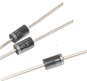
- Protective Component: A reverse-connected diode (typically a 1N4007) is visible across the coil terminals (paralleled between pins 13 and 14)—the freewheeling diode. It provides a discharge path for reverse induced voltage during de-energization, thereby protecting the control chip.
- The power input line for the common terminal COM (pin 1). This wire carries high-voltage power (220V AC) and supplies electricity to the motor.
- Wire gauge characteristics: This wire uses AWG 16-18 gauge, features thick insulation, and is typically brown or red in color, conforming to live wire identification standards.
- Where does it lead?
- This wire’s power source originates from the power plug. However, the 220V high-voltage power does not directly reach the relay. Its path is:
- Power plug L (live wire) -> Main fuse -> Main switch -> Fan speed switch/function selector switch -> Relay COM terminal (Pin 1).
- Typically, the COM terminal requires user selection (or MCU logic selection) to route power to a specific “standby” live wire of a designated relay. Only when the relay is energized does this energy get transmitted.
Chapter 3: Power Distribution Circuit for Normally Open (NO) and Normally Closed (NC) Terminals (Pins 3 and 4)
This is where the relay fulfills its ultimate purpose—directing electrical power to the correct load. In electric fans, the relay’s normally open (NO) and normally closed (NC) contacts are typically used for different functions, most commonly controlling the main winding (high speed) and auxiliary winding (such as the oscillating motor). This circuit will now be explained through specific scenarios:
Scenario 1: Adjusting Main Motor Speed (Most Common Application)
In multi-speed electric fans, the motor usually features a main winding and multiple tapped speed control windings (e.g., high speed, medium speed, low speed). Each speed setting corresponds to an independent relay. In this case, the relay’s NC terminal remains unused, while the NO terminal plays the primary role.
Pin 3 (NO) Connection:
When the relay closes, the live wire from the COM terminal is output through the NO terminal and connects to the corresponding speed terminal on the fan motor.
Example: For the “High Speed” relay, Pin 3 (NO) connects via a wire to the motor terminal marked ‘High’ or “L1”. At this point, the motor’s high-speed winding receives direct 220V voltage, causing the fan to operate at full speed.
Pin 4 (NC) Connection:
In multi-speed applications, the NC terminal typically remains open-circuited. For safety, it may be capped with an insulating cap or connected to the circuit for the next lower speed setting to form a chain logic. However, modern designs often feature independent control, leaving the NC terminal unused.
Scenario 2: Controlling Pan/Tilt Function (Classic Application)
In applications controlling pan/tilt functions, the SPDT relay serves as a dedicated relay specifically for controlling the pan/tilt motor.
Connection for Pin 1 (COM): It also connects to the live wire, providing “standby” power for subsequent circuits.
Connection for Pin 4 (NC): When the pan/tilt function is inactive, COM and NC are connected. Where does this wire connect? It may be connected to a current-limiting resistor or a small indicator light to show the pan function is in “standby” or “off” state.
Pin 3 (NO) connection: When the pan function is activated, the MCU controls the pan relay to energize, connecting COM to NO. This wire connects to one power line of the oscillating synchronous motor, while the other power line connects to the neutral wire. At this point, when the NO terminal is energized, the oscillating motor receives full 220V voltage, causing the motor to start operating and driving the fan head to swing left and right.
Through this design, the relay perfectly achieves the “on” and “off” function switching, converting the control signal into mechanical action.
Chapter 4: Knowledge Expansion and Safety Warnings
The distinct “click” sound from a relay indicates the engagement of its internal components—armature, core, and contacts.
Troubleshooting: If a fan speed setting fails to activate, first listen for the corresponding relay’s engagement sound. If audible, the issue likely lies in the NO terminal’s motor wiring or the motor itself. If silent, the problem originates from the control circuit (coil, driver tube, or MCU).
Critical Safety Warning!
Before any inspection or operation without professional expertise, remember: The interior of an electric fan involves 220V high-voltage electricity, which is extremely dangerous! Non-professionals must not touch any wiring while the unit is powered on. Even after power disconnection, capacitors may retain high voltage and require full discharge. All maintenance operations must be performed with the power completely disconnected and under the guidance of a qualified professional.
Conclusion: Understanding Industrial Design Wisdom Through Four Wires
By dissecting the circuitry of an electric fan’s relay through its four wires, we perceive more than just a cold schematic diagram. We witness the precise division of labor among subcomponents (separating control from power), the ingenuity of using low-voltage signals to manage high-voltage circuits, and the elegant logical distribution in design (achieving multifunctionality through switch-based switching). These four wires embody the three core principles of electrical design: safety, reliability, and efficiency.
Contact us immediately to learn how we can meet your cable and harness requirements. Follow us on Youtube .