Chapter 1: Pigtail Connectors—Definition, Structure, and Role
1.1 What Is a Pigtail Connector?
A pigtail, as the name suggests, is a short segment of optical cable featuring an exposed fiber core at one end and terminated by a standardized connector at the other. This “tail” serves to establish a movable connection between the optical fiber within the cable and equipment (such as optical modules or optical distribution frames) or other cables. Therefore, a pigtail connector (add hyperlink) refers to the core component installed at the end of the pigtail, enabling precise alignment and repeatable mating and unmating functionality.
A complete pigtail connector typically consists of the following components:
- Plug body: This forms the core of the connector, usually crafted from ultra-high precision, high-hardness materials such as ceramic (zirconia) or metal. It features a minute central aperture (typically 125μm or 126μm) designed to precisely secure and support the fiber core (commonly 9μm/50μm/62.5μm).
- Connector Housing: Protects the internal pin assembly and provides a locking mechanism for mating with adapters (flanges). Locking methods vary by interface type (e.g., LC snap-in, SC square push-pull, FC threaded).
- Cable Retention Assembly: Clamps the outer sheath of the pigtail cable, transferring stress from the cable to the connector housing to prevent core breakage under tension.
- Rear Housing: Protects the fiber-connector interface and provides bending radius protection.
- The ultimate goal of pigtail connectors is to achieve precise axial alignment of the cores from two fibers at the connection point. This enables optical signals to transmit from one fiber to another with minimal loss (insertion loss) and reflection (return loss).
1.2 The Role of Pigtail Connectors in Networks
Pigtail connectors serve as the “joints” in optical networks, permeating every corner of the infrastructure:
- Device Connectivity: They link the optical ports of switches, routers, servers, and other equipment to the optical distribution system.
- Optical Distribution Frames (ODFs): Pigtails are extensively used on ODFs to facilitate cross-connections and manage the patch cords between backbone cables and device ports.
- Network Splitting and Merging: In systems like WDM and PON, pigtail connectors link to passive components such as splitters and wavelength division multiplexers.
- Testing and Diagnostics: Utilize pigtails to connect test equipment (e.g., OTDRs, optical power meters) for network performance monitoring and fault localization.
Indeed, without pigtail connectors, all optical fibers would remain isolated “information silos,” incapable of forming flexible, manageable optical networks.
Chapter 2: Why Use Pigtail Connectors? — Necessity and Core Value
While fiber optic connections can be permanently established through fusion splicing, why use removable pigtail connectors? Their value lies in multiple dimensions, including flexibility, manageability, and reliability.
2.1 Enabling Flexibility and Modularity
This represents the fundamental value of pigtail connectors. Modern networks require frequent configuration changes, capacity expansions, and maintenance. If all connections were permanently fused, replacing any device, adjusting ports, or altering routing would become an extremely difficult and costly endeavor. Pigtail connectors enable:
- Plug-and-Play: Devices can be rapidly added to or removed from the network.
- Convenient Cross-Connecting: Network topology can be altered with simple patch cord insertion/removal at patch panels, delivering high flexibility.
- Modular Design: Equipment manufacturers can pre-assemble connectorized optical modules, simplifying device production and end-user installation.
2.2 Reducing Installation and Maintenance Costs
While a single fusion splice point costs less than a connector, the efficiency gains from connectors are substantial when viewed holistically.
- Pre-termination: Pigtails and patch cords undergo standardized, batch termination in factory environments, ensuring consistent quality. On-site installation requires only plug-and-play, drastically reducing construction time and lowering skill requirements for installers.
- Rapid fault recovery: When a link or device port fails, maintenance personnel can directly replace patch cords or pigtails to quickly isolate and resolve issues without complex splicing operations.
2.3 Ensuring Reliable Performance
High-quality pigtail connectors are factory-terminated with precision-ground end faces and automated inspection, guaranteeing extremely low and stable insertion loss and return loss. This far surpasses the variability of field operations, ensuring consistent performance across the entire link.
2.4 Facilitating Testing and Monitoring
Network testing and maintenance are routine tasks. The presence of pigtail connectors allows technicians to conveniently connect instruments like optical power meters and OTDRs for segmented testing, performance evaluation, and fault diagnosis—capabilities unavailable at fusion-spliced points.
Chapter 3: Types of Pigtail Connectors: Applications in Different Scenarios
Pigtail connectors come in numerous types. The following introduces six of the most common and important types.
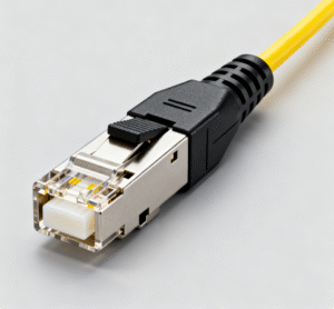
3.1 LC Connectors
- Appearance and Structure: Standard square housing with a modular jack (RJ-45) latching mechanism, producing a distinct “click” sound during insertion/removal. Pin diameter: 1.25mm.
- Features and Advantages:
- High Density: Compact size is its primary advantage, occupying approximately 50% less space per connector than SC. It enables deployment of double the port count within the same space, making it ideal for high-density applications like data centers and core switches.
- Stable Performance: The snap-in design ensures a stable and reliable connection with excellent shock resistance.
- Mainstream Choice: It has become the most prevalent interface type in data centers and enterprise networks, particularly well-suited for pairing with small form-factor optical modules like SFP and SFP+.
- Typical Applications: High-speed data center networks, high-density fiber optic distribution frames, optical module interfaces for telecom equipment.
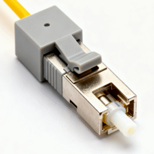
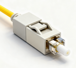
3.2 SC Connector
- Appearance and Structure: Square housing with a push-pull locking mechanism for simple operation. Pin diameter: 2.5mm.
- Features and Advantages:
- Excellent Stability: The push-pull design ensures a secure connection resistant to accidental disengagement. Enhanced stability in environments with frequent vibration.
- Moderate Cost: Mature manufacturing processes enable competitive pricing.
- Former Mainstream Choice: Before LC adoption, SC was the dominant selection for enterprise and access networks, extensively used in GBE and PON systems.
- Typical Applications: Fiber-to-the-Home (FTTH) terminal optical modems, enterprise internal network cabling, and local area networks.
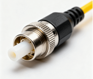
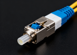
3.3 FC Connector
- Appearance and Structure: Circular metal housing with threads, secured by a locking nut. Pin diameter: 2.5mm.
Features and Advantages:
- Exceptional Stability: The threaded locking mechanism provides the most reliable mechanical connection, virtually immune to loosening from external forces, making it ideal for high-vibration environments.
- High Alignment Precision: Metal housing and threaded structure ensure precise centering alignment.
- Disadvantages: Slower installation and removal speed, unsuitable for high-density applications requiring frequent plugging and unplugging.
- Typical Applications: Test instruments (e.g., OTDR), cable television networks, base station antenna feeders, and other industrial environments sensitive to vibration and requiring long-term stability.
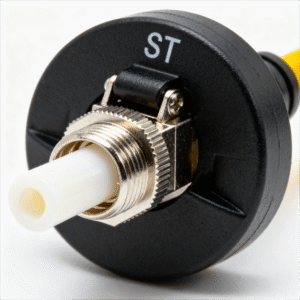
3.4 ST Connector
- Appearance and Structure: Circular bayonet-style design, similar to BNC connectors, featuring a semi-circular rotation lock via a bayonet mechanism. Pin diameter: 2.5mm.
- Features and Advantages:
- Installation Convenience: Bayonet design enables faster installation than FC’s threaded connection.
- Disadvantages: Bayonet design offers less stability than push-pull or threaded connections, prone to accidental disengagement from pulling, and exhibits poor vibration resistance.
- Typical Applications: Primarily used in legacy enterprise networks and fiber LANs; rarely adopted in new projects.
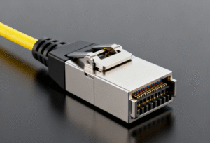
3.5 MPO/MTP® Connectors
- Appearance and Structure: This multi-fiber connector houses 12, 24, or more fibers within a single housing. MTP® is US Conec’s optimized upgrade of the MPO connector, offering superior performance.
- Features and Advantages:
- Ultra-High Density: A single MPO connector replaces 12 or 24 LC connectors, dramatically increasing port density while saving significant space and installation time.
- Pre-terminated Trunking: Primarily used in data center 40G/100G/400G parallel optical transmission systems as a pre-terminated solution for trunk cables.
- Polarization and Keyway:Complex structure with strict up/down correspondence and guide pin orientation requirements necessitating precise planning.
- Typical Applications: Backbone connections in large data center spine-leaf architectures and high-performance computing clusters.
3.6 End-Face Polishing Types: PC, UPC, APC
Beyond the physical interface, the end-face polishing process is another critical factor determining connector performance, particularly return loss.
- PC: Features a micro-spherical end face, the earliest polishing method now rarely used.
- UPC: Features a more precise spherical end face, achieving return loss exceeding -50dB. It is the mainstream choice for current data communications (blue ferrule).
- APC: Features an 8-degree beveled end face that allows reflected light to escape the core rather than return along the same path, achieving return loss exceeding -60dB. Primarily used in reflection-sensitive systems such as analog video transmission and PON networks (green ferrule).
Chapter 4: How to Select the Right Pigtail Connector and Apply It Correctly
4.1 Selection Criteria:
| Selection Factors | Key Considerations | Typical Selection |
| 1.Application Scenariosand Device Interfaces | Device optical module type, patch panel port type. | Data Centers/High-Speed Networks: LC; FTTH/Enterprise Networks: SC; Test Equipment/High-Vibration Environments: FC; 40G/100G+ Data Center Backbones: MPO/MTP. |
| 2.Port Density Requirements | Is cabinet/panel space limited? | High density: LC (simplex/duplex) or MPO; Low density requirements: SC or FC. |
| 3. Performance Metrics | Insertion Loss (IL) and Return Loss (RL) Budget. | General Data Communication: UPC; Analog Video, PON: APC. Select an IL value grade superior to the system budget (e.g., <0.2dB Premium grade). |
| 4. Physical Environment | Is there vibration? Is frequent plugging and unplugging required? | High-vibration/industrial environments: FC; Frequent insertion/removal in data centers: LC; Stable cabling in patch panels: SC. |
| 5. Cost and Existing Architecture | Project budget and compatibility with existing equipment. | For new projects, prioritize mainstream LC connectors; Expansion must be compatible with existing SC/FC equipment. |
| 6. Fiber Optic Type | Single-mode (SM) or multi-mode (MM). | Select connectors suitable for the corresponding fiber type (with slight variations in internal structure). Single-mode fibers typically use LC/SC/FC connectors, while multi-mode high-speed parallel connections use MPO connectors. |
4.2.1 Installation and Termination
There are two primary methods for terminating pigtails:
- Field polishing: Requires high technical skill, and quality is difficult to guarantee.
- Pre-terminated: Strongly recommended. Purchase factory-terminated pigtails for consistent, reliable quality.
- On-site, only one step is required: Cleaning! This is the most critical step. Use a dedicated lint-free wipe and a microscope to meticulously clean the connector end-face and the device’s optical port before connection.
- Inspect End-Faces: Use an optical fiber microscope to check for scratches, dust, or contaminants.
- Insert/Remove with Care: Align with the adapter, insert smoothly until a “click” confirms secure locking. When removing, always press the release button (e.g., LC) first, then pull straight out vertically. Never pull directly on the cable.
4.2.2 Cabling and Management
- Ensure Minimum Bend Radius: Adhere to the cable’s minimum static/dynamic bend radius (typically 10-20 times the cable’s outer diameter) during installation to prevent signal attenuation from excessive bending.
- Use Cable Management Tools: Employ cable management rings, zip ties, and similar tools within cabinets to keep cables organized and orderly, avoiding crossings, compression, and overly tight bundling.
- Labeling: Apply clear, durable labels to both ends of each pigtail, indicating source and destination. This forms the foundation for efficient operations and maintenance.
4.2.3 Testing and Acceptance
Use an optical power meter to test link insertion loss, ensuring values remain within system budget limits.
Employ an OTDR to locate fault points, splice loss, and reflection events within the link.
4.2.4 Routine Maintenance
Regular Inspections: Periodically spot-check connector end-face cleanliness.
Establish a Spare Parts Inventory: Stock various cleaning tools and a small quantity of commonly used pigtails for emergency use.
Standardize Operational Procedures: Train maintenance personnel to adopt the professional habit of “clean first, connect later.”
Chapter 5: Conclusion and Outlook
Pigtail connectors have evolved technologically from FC and ST to SC, and now to the LC connectors dominating data centers today and the future-oriented MPO. While connector form factors change, their core mission remains unchanged: to achieve “seamless” optical signal transmission with minimal loss and maximum reliability.
Drawing on 28 years of experience in the cable assembly industry, JinHai has developed its own design and selection philosophy, which we apply in practical solutions. Our emphasis on precision engineering, cleanroom management, and standardized operations is key to delivering reliable, stable fiber optic cables. Simultaneously, we continuously explore the application of new materials and technological advancements. Choose JinHai, and we will help your project succeed quickly!