Chapter 1: Introduction
In today’s highly interconnected digital age, we encounter a seemingly ordinary yet critically important component almost daily—the USB cable. As the most commonplace power connection cable in modern digital life, it has become integral to our devices such as smartphones, computers, and printers. Below, I, a seasoned cable design expert, will guide you through an in-depth analysis of USB cable design, manufacturing processes, key quality control points, and its intricate functional systems.
Chapter 2: USB Cable Design
USB cable design is a systematic engineering endeavor that balances electrical performance, physical structure, and signal integrity.
2.1 Evolution of Standards and Protocols: The Design Framework
The USB standard dictates cable design. Initially focused solely on 480Mbps transfer speeds, it later evolved to support ultra-high-speed transmission alongside full functionality (such as power delivery, interface detection, and analog audio). This progression propelled the USB transmission protocol from the USB 1.0/1.1 era to the current USB-C and USB4/Thunderbolt 3/4 era. A USB cable compliant with USB-C and USB4/Thunderbolt 3/4 protocols features a 24-pin connector. Its accompanying full-function cable possesses an extremely complex internal structure. Below, I will outline the functions of its internal components:
Multi-Channel Operation: USB4, based on the Thunderbolt 3 protocol, supports up to four high-speed data lanes. These lanes can be dynamically configured for data transfer or Display Port video output.
Significant increase in conductor count: A full-function USB4/Thunderbolt 3 passive cable may contain up to 16 to 20 conductors or more, including:
- 2 differential pairs for USB 2.0 data.
- 4 differential pairs for high-speed data (USB4/DisplayPort) (two pairs each for TX/RX).
- 2 VBUS power lines (typically thicker gauge or parallel-wired to carry high currents).
- 2 GND ground lines.
- 1 CC (Configuration Channel) line for interface detection, direction identification, power negotiation, and Alternate Mode negotiation—the heart of USB-C.
- 1 VCONN line, powering the electronic marker chip (E-Marker) within the cable.
Possibly an SBU (Sideband Use) line for analog audio or DisplayPort auxiliary channels.
E-Marker chip: This is the core of high-speed/high-power USB-C cables. A tiny chip embedded within the connector stores critical cable information: supported USB protocol versions (e.g., USB 3.2 Gen2, USB4), current capacity (3A or 5A), DisplayPort Alternate Mode support, etc. Devices read this information via the CC line to determine operating mode and power delivery. Cables without an E-Marker have severely limited functionality (typically supporting only USB 2.0 speeds and 3A current). Cables without an E-Marker have severely limited functionality (typically supporting only USB 2.0 speeds and 3A current).
2.2 Electrical Performance Design: The Foundation of Speed and Power
Characteristic Impedance Control: High-frequency signals encounter characteristic impedance when transmitted through conductors. Mismatched impedance causes signal reflection, severely degrading signal quality. Therefore, high-speed data pairs (such as differential pairs in USB 3.x and USB4) must be precisely designed to ensure their differential impedance remains stable at 90Ω.
Attenuation: Signal energy gradually diminishes during transmission, with higher frequencies experiencing greater loss. Designers must select insulating materials with low dielectric constants and low loss tangents (e.g., foamed polyethylene) while balancing cable length. USB4 certification imposes extremely stringent attenuation limits, typically restricting passive cable lengths to no more than 0.8 meters.
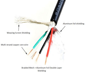
Crosstalk: Electromagnetic interference between adjacent conductors weakens signal transmission. Twisted pairs with individual aluminum foil shielding (separate shielding for each differential pair) serve as standard crosstalk mitigation. Additional shielding layers around the cable jacket provide further protection against interference.
DC Resistance: This directly impacts power transmission efficiency. To support charging at 100W (20V/5A) or even 240W (48V/5A), the VBUS and GND conductors must be sufficiently thick to minimize resistance, reduce voltage drop, and limit heat generation. The USB-IF specifies clear upper limits for cable DC resistance.
2.3 Physical Structure Design: Ensuring Reliability
Conductor Material: Oxygen-free copper (OFC) is the most commonly used material due to its superior conductivity. Tin-plated copper or thicker solid copper wires (rather than multiple thin strands) are employed in higher-end cables, as these materials better minimize high-frequency signal loss.
Insulation Materials: Examples include PVC (low cost, good flexibility, but may contain halogens), TPE (environmentally friendly, flexible), and PE (commonly used for high-speed data cable insulation).
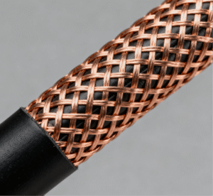
Shielding Structure: The shielding design employs multiple layers. First, individual aluminum foil layers shield each conductor. Then, a braided metal mesh (tin-plated copper) provides overall shielding for comprehensive protection.
Grounding: The shielding layer must be effectively connected to the device’s grounding point via a drain wire or the connector housing. Failure to do so significantly reduces shielding effectiveness.
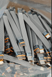
Outer Jacket and Tensile Strength Fibers: The outer jacket requires properties such as abrasion resistance, bend resistance, and flame retardancy. Many high-quality cables incorporate nylon or Kevlar fibers internally as tensile members, greatly enhancing durability and preventing internal jacket fractures caused by frequent plugging/unplugging and bending.
Chapter 3: Manufacturing USB Cables
The transformation of USB cables from design blueprints into physical products relies on highly automated production lines.
3.1 Wire Drawing and Stranding
High-purity copper rods are drawn through multiple dies into fine copper wires of the required diameter. Multiple fine copper wires are then twisted together to form a stranded conductor, ensuring the cable’s flexibility.
3.2 Extrusion Insulation
The copper conductor passes through an extruder, uniformly coated with a layer of plastic insulation material (such as PE). During this process, the temperature of the raw material and the extrusion speed control the uniformity and roundness of the insulation layer, directly affecting impedance stability.
3.3 Pair Twisting
For differential data cables, two insulated conductors are twisted together with precise, constant pitch. This critical step ensures signal integrity and suppresses common-mode interference. Pitch control is achieved using a precision twisting machine.
3.4 Cable Assembly
All conductors—power lines, ground wires, and multiple differential signal pairs—are arranged according to design specifications. Simultaneously, drain wires and tensile fibers are incorporated. This process ensures structural stability and roundness of the cable.
3.5 Shielding
The assembled cable core passes through a shielding machine, sequentially undergoing aluminum foil wrapping and braided mesh weaving. The density (coverage rate) of the braided mesh is a critical metric for evaluating shielding effectiveness.
3.6 Outer Jacket Extrusion
Finally, the outermost sheath is extruded onto the cable. Color masterbatch may be mixed into the sheath material to produce different colors.
3.7 Cable Testing
Before cutting, preliminary electrical tests are conducted on the entire cable reel, including continuity testing, short-circuit testing, and insulation withstand voltage testing.
3.8 Terminal Crimping and Injection Molding
This stage involves manufacturing the connectors.
Cutting and Stripping: Cables are cut to specified lengths. Precision cutting machines strip specific lengths of outer jacket, shielding, and core insulation from both ends, exposing the conductors.
Terminal Crimping: Exposed copper wires are inserted into corresponding positions within USB connectors. High-precision crimping machines firmly secure the terminals to the conductors. Crimp quality directly determines connection reliability and resistance values.
Soldering: For more complex connectors (e.g., USB-C), soldering may replace crimping.
Housing Assembly: Assemble the crimped cable with the plastic housing.
Injection Molding: This critical step creates a robust connector. The assembled connector is placed in a mold, where molten plastic is injected to form a durable “stress relief” sleeve at the terminal-cable junction, preventing internal fractures during bending.
3.9 E-Marker Chip Programming and Soldering
For cables requiring E-Markers, pre-programmed chips must be soldered onto specific contacts of the USB-C connector before injection molding.
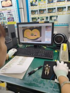
3.10 100% Final Testing
This is the final and most critical quality assurance step before shipment. Each finished cable undergoes comprehensive testing on a multifunction tester, including:
– Connectivity/Wiring Diagram Test: Verifies correct pin connections with no shorts, opens, or misalignments.
– DC Resistance Test: Measures resistance between VBUS and GND to ensure compliance.
– High-Voltage Insulation Test: Applies voltage between conductors and between conductors and shielding to assess insulation strength.
Signal Integrity Testing (for high-speed cables): Utilizes network analyzers or time-domain reflectometers (TDR) to measure characteristic impedance and insertion loss, verifying compliance with USB-IF specifications.
E-Marker Information Read Verification: Confirms the accuracy of chip information.
Only cables that pass all tests are packaged and shipped.
Chapter 4: Critical Control Points
During the design and manufacturing process, the following stages represent core critical control points that determine the final performance and quality of cables:
4.1 Characteristic Impedance Control: This is the core of high-speed cables. From the selection of insulating materials and the uniformity of extrusion to the precision of the twisted pair pitch, any deviation can cause impedance mismatch, leading to signal reflection and rendering high-speed transmission unstable or even impossible.
4.2 Shield Integrity: The coverage rate (braid density) and grounding method of the shield form the fortress against electromagnetic interference.
4.3 Conductor DC Resistance: The use of high-quality copper is crucial for ensuring stable power transmission.
4.4 E-Marker Chip Authenticity and Accuracy: This serves as the “identity card” for the functional integrity of USB-C cables. The E-Marker chip ensures devices output voltages or currents within their tolerable range, preventing equipment damage.
4.5 Termination Point (Crimping/Soldering) Quality and Stress Relief Design: Most cable failures occur at interface connections. Superior crimping ensures low resistance and mechanical strength, while well-engineered injection-molded stress relief structures effectively distribute bending stress, significantly extending cable lifespan.
4.6 Material Compliance and Durability: Cable jackets and insulation materials must meet environmental (e.g., RoHS, REACH) and flame-retardant (e.g., UL94 V-0) standards.
Chapter 5: Functional Analysis
The functionality of USB cables has long surpassed their original purpose, evolving into highly integrated, multi-functional cables.
5.1 Core Foundational Functions
Data Transfer: This represents USB’s original definition. From early 1.5Mbps to today’s 80Gbps (USB4 v2.0), increased speeds enable it to handle diverse demands—from keyboards and mice to high-speed NVMe SSD portable drives.
Power Delivery: Evolving from the initial 5V/0.5A (2.5W) to current standards:
USB Power Delivery (PD) 3.1 Protocol: Supports up to 48V/5A, delivering 240W of power—sufficient to drive high-performance laptops, monitors, and even some small appliances.
Other Fast Charging Protocols: Such as QC (Qualcomm), AFC (Samsung), FCP/SCP (Huawei), etc. These protocols are typically negotiated over the D+/D- lines in USB-A to USB-C cables.
5.2 Advanced Integration Features (Primarily via USB-C)
Alternate Mode: One of USB-C’s most revolutionary capabilities. Through Alternate Mode, USB-C ports and cables can “transform” into other types of video or data interfaces.
DisplayPort Alternate Mode: The most prevalent video mode, enabling direct transmission of native DisplayPort signals to support high-resolution and high-refresh-rate displays. This allows a single cable to handle data transfer, video output, and device charging simultaneously, achieving true multifunctional integration and optimizing space utilization.
Audio Adapter Accessory Mode: Permits the USB-C port to replace traditional 3.5mm headphone jacks.
Thunderbolt 3/4: Thunderbolt technology is now integrated with USB4. Thunderbolt 3/4 cables are essentially the most capable USB-C cables, mandating support for 40Gbps data transfer, DisplayPort video output, and 100W PD charging. Passive Thunderbolt cables demand extremely high performance, while active cables incorporate signal conditioning chips internally to extend transmission distances.
Chapter 6: Summary
The above overview of USB cables is based on JinHai’s proprietary intellectual property. While a USB cable may appear simple, its actual manufacturing process is far from straightforward. As a professional custom cable/cable harness manufacturer, JinHai is confident that our products will accelerate your project’s path to success.
Contact us immediately to learn how we can meet your cable and harness requirements. Follow us on Youtube .